Material knowledge
Hardness scales
Hardness is the most common callout on a hard-steel drawing. The number only means something together with the test that produced it. This page covers 6 scales, a conversion table and a callout format. Heat treater and inspector then read the drawing the same way.
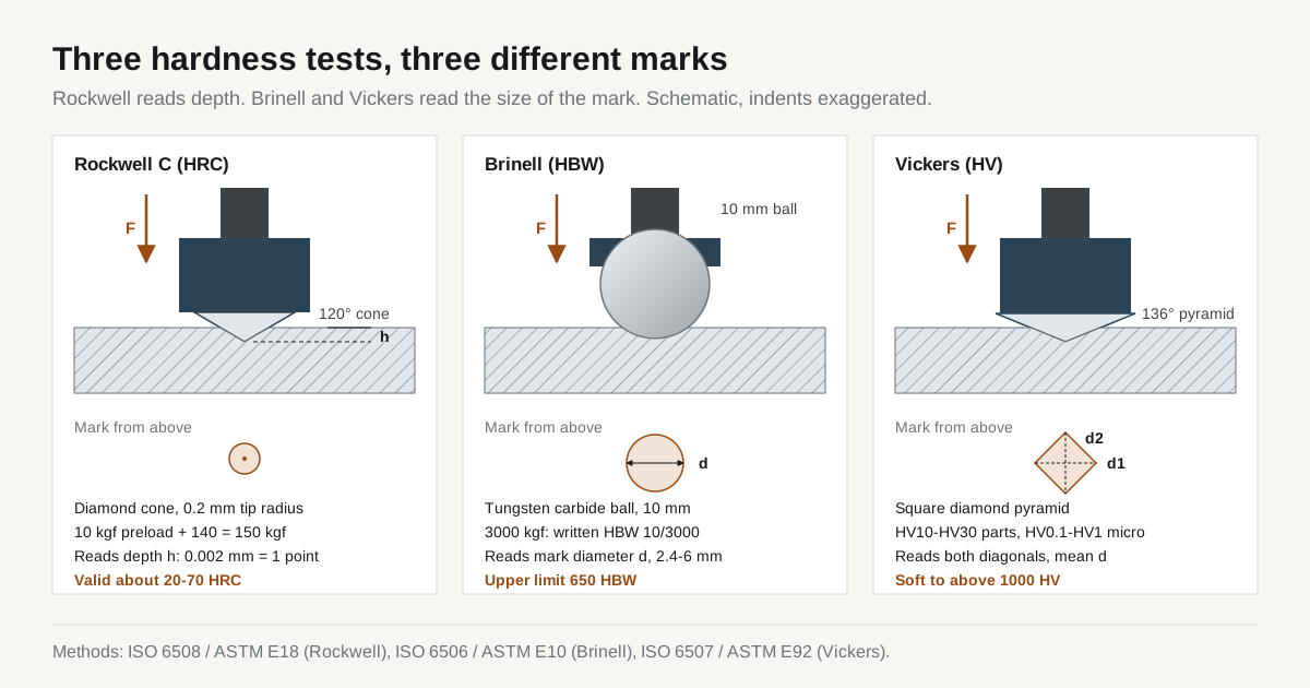
| Rockwell C (HRC) | Diamond cone, 150 kgf total. Valid about 20-70 HRC. Default for hardened tool steel |
|---|---|
| Rockwell B (HRB) | 1/16 in ball, 100 kgf. Annealed and soft steel up to about 100 HRB |
| Brinell (HBW) | 10 mm carbide ball, 3000 kgf. Plate, forgings, annealed bar. Upper limit 650 HBW |
| Vickers (HV) | Diamond pyramid. HV10-HV30 on parts, HV0.1-HV1 for case depth profiles |
| Knoop (HK) | Elongated diamond, very shallow mark. Coatings and thin layers |
| Leeb (HLD) | Portable rebound test. Large, heavy parts. Result is converted, not direct |
| Minimum thickness, HRC | About 10x the indent depth: roughly 0.8 mm at 60 HRC |
| Usual tolerance band | 3-4 HRC points, for example 58-62 HRC |
| Conversion standards | ASTM E140 and ISO 18265. Approximate for any single grade |
Hardness as a test result
Hardness is resistance to a defined indenter under a defined load. It is a test result, not a material constant.
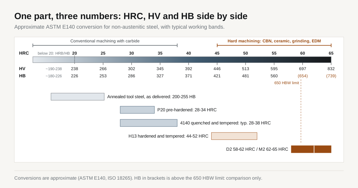
A D2 block at 60 HRC converts to about 697 HV. Brinell is not used at that level: 60 HRC sits at the 650 HBW limit of the carbide ball.
Each test responds differently to the matrix, the carbides and the elastic recovery of the steel. That is the reason conversion tables are approximate and acceptance tests use the scale named on the drawing.
Rockwell scales: HRC, HRB, HRA and superficial
Rockwell measures depth. A preload of 10 kgf seats the indenter, the full load is applied, then removed. The tester reads the remaining depth increase h.
On HRC each point equals 0.002 mm of depth, so HRC = 100 - h/0.002 mm. A softer part takes a deeper mark and reads a lower number.
| Scale | Indenter | Total load | Typical use on steel |
|---|---|---|---|
| HRC | 120° diamond cone, 0.2 mm tip radius | 150 kgf | Hardened steel, about 20-70 HRC |
| HRB | 1/16 in (1.588 mm) ball | 100 kgf | Annealed and soft steel, up to about 100 HRB |
| HRA | Diamond cone | 60 kgf | Carbide, very hard thin parts |
| HR15N / HR30N / HR45N | Diamond cone, 3 kgf preload | 15 / 30 / 45 kgf | Thin sections, shallow case layers |
Rockwell C is the default for hardened tool steel. Annealed tool steel at 200-255 HB is below the valid HRC range and goes on HRB or Brinell.
Thin sections and curved surfaces
ISO 6508 requires a thickness of at least 10x the permanent indent depth. At 60 HRC the depth is about 0.08 mm, so the minimum thickness is about 0.8 mm. A bulge or mark on the back side makes the reading invalid.
Convex cylinders read low. Below about 25 mm diameter, ASTM E18 and ISO 6508 give correction values that the inspector adds to the reading. Thin or small parts move to superficial Rockwell or Vickers.
Brinell: HBW on plate, forgings and annealed bar
Brinell presses a 10 mm tungsten carbide ball into the part at 3000 kgf. The diameter d of the round mark is read under a low-power microscope. The result is written as HBW 10/3000, or just HBW.
The mark is large, 2.4-6 mm across. It averages over coarse microstructure, so Brinell suits castings, forgings, plate and annealed bar. Wear plate at 400-500 HB and incoming tool steel at 200-255 HB are typical Brinell work.
ASTM E10 and ISO 6506 set an upper limit of 650 HBW. That is about 59-60 HRC. Above roughly 45 HRC the conversion values assume the carbide ball, and above 650 HBW they are comparison figures only.
Vickers and Knoop: case depth and thin layers
Vickers uses a square diamond pyramid with 136° between opposite faces. Both diagonals of the mark are measured and averaged. HV = 1.8544 × F / d², with F in kgf and d in mm.
One scale covers the whole range, soft to above 1000 HV. That makes Vickers the scale for:
- Case depth profiles. A sectioned sample is tested at HV0.5 or HV1 from the surface inward.
- Nitrided layers and thin sections. Low loads keep the mark inside the layer.
- Small features. Punch tips, thin blades, pins under 3 mm.
- Disputes. Vickers is the reference method when two Rockwell readings disagree.
Micro-Vickers values at HV0.1 and below read higher than HV10 on the same steel. The drawing should fix the load, for example 700 HV1, not just 700 HV.
Knoop (HK) uses an elongated diamond with a 7:1 diagonal ratio. The mark is shallow, about 1/30 of its long diagonal, so it suits coatings and steep hardness gradients. The method is in ASTM E384.
Leeb and other portable testers
Leeb testers fire an impact body at the surface and compare rebound to impact velocity. The result in HLD is converted to HRC or HB by a material curve. ASTM A956 and ISO 16859 cover the method.
Leeb suits large dies, rolls and press beds that cannot go on a bench tester. The D device needs a solid part of several kilograms, a minimum thickness and a ground surface. Small parts must be coupled to a heavy base, or tested on a bench machine instead.
Ultrasonic contact impedance testers (ASTM A1038) press a small Vickers diamond and work on smaller parts. Both methods give converted values and fit in-process checks better than final acceptance.
Conversion table: HRC, HV, HB and tensile strength
Values below follow the ASTM E140 table for non-austenitic steel, rounded. The tensile column is the approximate ISO 18265 relation for steel.
| HRC | HV | HBW (10 mm, 3000 kgf) | Approx. tensile strength, MPa |
|---|---|---|---|
| 20 | 238 | 226 | 770 |
| 25 | 266 | 253 | 860 |
| 30 | 302 | 286 | 965 |
| 35 | 345 | 327 | 1110 |
| 40 | 392 | 371 | 1260 |
| 45 | 446 | 421 | 1430 |
| 50 | 513 | 481 | 1650 |
| 55 | 595 | 560 | 1920 |
| 60 | 697 | (654) | not defined |
| 65 | 832 | (739) | not defined |
HB in brackets is above the 650 HBW limit and is for comparison only. Tensile strength is not given above about 55 HRC. Fully hardened tool steel fails by fracture with little yielding, so a tensile figure there has no practical use.
Why conversions are approximate
Each conversion table is built from tests on a set of steels, not derived from physics. Work hardening, elastic modulus and carbide content change how each indenter responds. A carbide-rich grade such as D2 or M2 can sit 1-2 HRC away from the converted value.
ASTM E140 and ISO 18265 both say converted values do not replace a measured value. Conversion is for orientation only.
If the drawing says 700 HV1, the part is tested in HV1. If it says 60 HRC, it is tested in HRC.
Typical working hardness by grade
| Grade | Condition | Typical hardness |
|---|---|---|
| D2, H13, A2 | Annealed, as delivered | 200-255 HB |
| P20 | Pre-hardened | 28-34 HRC |
| 4140 | Pre-hardened (quenched and tempered) | 28-32 HRC |
| H13 | Hardened and tempered | 44-52 HRC |
| D2 | Hardened and tempered | 58-62 HRC |
| M2 | Hardened and triple tempered | 62-65 HRC |
The heat treatment behind each band is on heat treatment of tool steel. The full grade list is on the materials overview.
Hardness and the machining route
Hardness at the time of cutting decides the process, the tool and most of the cost. The bands below are typical and depend on grade and geometry. Confirm the route per drawing.
| Hardness when cut | Usual route | Notes |
|---|---|---|
| Below 30 HRC (annealed, pre-hardened) | Conventional milling and turning, carbide | P20 and 4140 are cut finished at 28-34 HRC |
| 30-45 HRC | Coated carbide at reduced speed | Tool life drops fast above about 40 HRC |
| 45-55 HRC | Hard milling, hard turning | Coated carbide, CBN for turning |
| 55-65 HRC | CBN, grinding, wire EDM | Most fine features are ground or eroded |
A part that reads 2 points above its band moves tool life noticeably at 60+ HRC. A tight hardness band also makes the machining cost more predictable.
Hardness callouts on the drawing and RFQ
Range and scale. Write a band with the scale: 58-62 HRC. A band of 3-4 points is normal. “Hardened” or “58 HRC min.” leaves the result open.
Test load for Vickers. Write the load with the value: 650 HV10, or 700 HV1 for a thin layer.
Test location. Name a non-functional test surface, or call for a test coupon from the same batch. Add the number of readings, for example 3 readings per part, mean within the band.
Case and layer depth. State depth, limit hardness and test load. Typical formats:
- Case hardening:
CHD 0.8-1.2 mm @ 550 HV1, surface 58-62 HRC, core 30-45 HRC (ISO 18203). - Nitriding:
NHD 0.15-0.25 mm, limit core hardness + 50 HV, surface min. 900 HV0.5. - US practice: effective case depth 0.8-1.2 mm to 50 HRC (SAE J423). The 50 HRC limit is about 513 HV, not 550 HV, so the 2 formats give different depths.
Sampling. Say whether hardness is checked on every part, on a sample per batch or on a coupon. That decides inspection cost.
Case depth and nitriding are covered on surface hardening. What a heat treat certificate should show is on material certificates.
Test practice on real parts is in hardness testing tool steel parts. Terms such as CHD and NHD are in the glossary.
Background on the methods: Rockwell scale and Vickers hardness test. A drawing with a hardness callout can go straight to the RFQ form.
Common questions
HRC or HV on a tool steel drawing?
HRC for most through-hardened parts thicker than about 1 mm. It is fast, cheap and every heat treater and shop has a Rockwell tester. HV fits thin sections, small features, nitrided or case-hardened layers and coatings. There the Rockwell cone would punch through the hard layer. A drawing can carry both: HRC for the core or bulk hardness and HV for a surface layer.
Accuracy of HRC to HV conversion?
Approximate only, typically within 1-2 HRC points on plain and low-alloy steel. High-carbide grades such as D2 and M2 can deviate further, because cone and pyramid respond differently to hard carbides. ASTM E140 and ISO 18265 both state that converted values are not equivalent to measured values. For acceptance, test on the scale written on the drawing.
Brinell testing above 60 HRC?
No. ASTM E10 and ISO 6506 limit the carbide ball to 650 HBW, which is about 59-60 HRC. Above that the ball itself starts to deform and the reading stops being valid. The HB values above 650 in conversion charts are for comparison only. Hardened tool steel is tested on Rockwell C or Vickers.
Hardness test marks on finished parts?
A Rockwell C mark is about 0.5-1 mm across and a Brinell mark 2.4-6 mm. On a lapped seal face or a polished mould cavity that is a defect. The drawing should name a test surface that is non-functional, or call for a test coupon heat treated with the parts. Vickers micro marks are small but still visible under magnification.
Hardness tolerance band for hardened tool steel?
3-4 HRC points is the normal band, for example 58-62 HRC on D2 or 44-48 HRC on an H13 die. A 2-point band such as 60-62 HRC can be held. It leaves little room for section-size variation and tester repeatability of about 1 point. A minimum-only callout such as 58 HRC min. leaves the upper end open and should be avoided on parts that need toughness.
Leeb readings for acceptance?
Only by agreement, and only on large parts. Leeb testers convert a rebound velocity into HRC or HB using a material curve. The result depends on mass, thickness and surface finish. The D-type device needs a part of several kilograms or a coupling to a heavy base. Leeb suits large dies and rolls that cannot go on a bench tester.