Machining process
Wire EDM
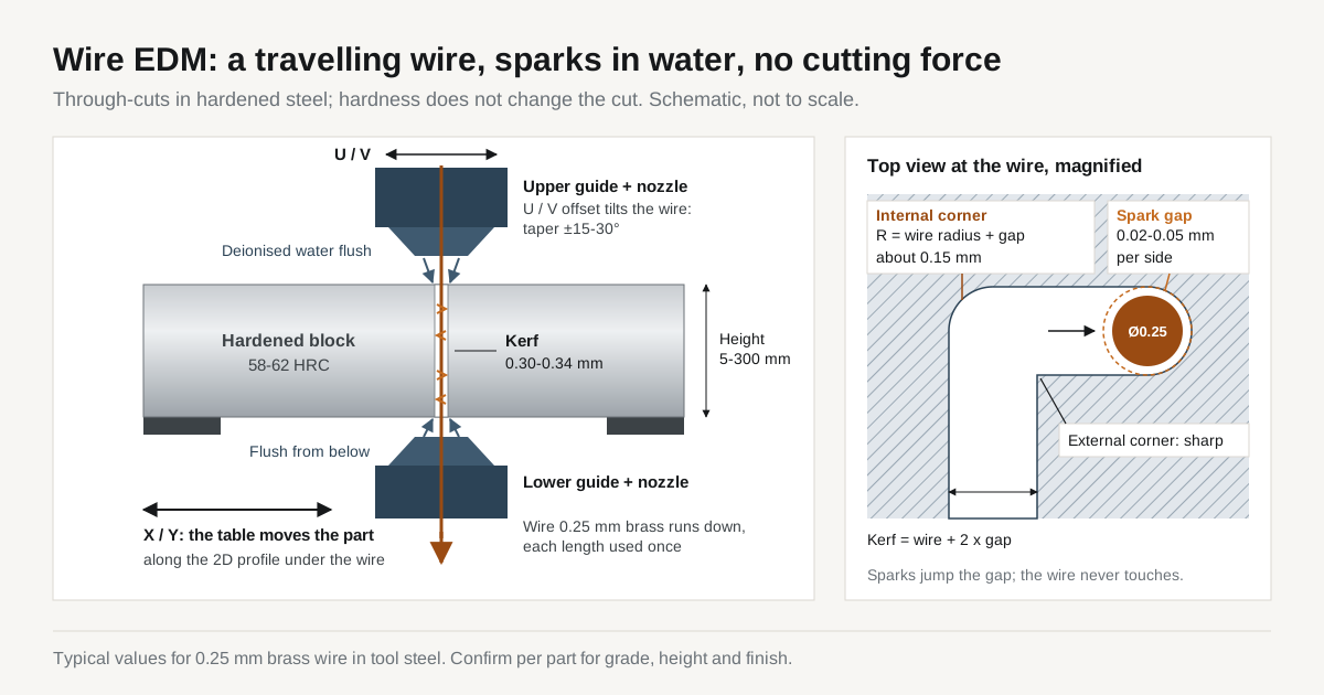
A thin brass wire erodes hardened steel with sparks in deionised water. It follows a 2D profile through the full part height, with no cutting force. Punches, die openings and strippers in 55-64 HRC steel are cut this way.
| Principle | Spark erosion in deionised water; no contact, no cutting force |
|---|---|
| Hardness | Not a factor; 62 HRC D2 cuts at about the same rate as annealed steel. The part must conduct electricity |
| Wire | Brass or coated brass, 0.25 mm standard; 0.10-0.20 mm for fine detail and small corners |
| Kerf | Wire diameter + 2 x spark gap; about 0.30-0.34 mm with a 0.25 mm wire |
| Smallest internal corner | About R0.15 mm with 0.25 mm wire; about R0.07 mm with 0.10 mm wire |
| Accuracy | ±0.005 mm typical with 2-4 skim cuts; ±0.002-0.003 mm best case on short profiles; ±0.01-0.02 mm single cut |
| Surface finish | Ra 2-3.5 µm single cut; Ra 0.4-0.8 µm after 3-4 passes |
| Recast layer | 15-30 µm after the rough cut; 2-5 µm after the final skims |
| Taper | ±15-30° on most machines, depending on guides and part height |
| Typical parts | Punches, die openings and buttons, stripper and retainer plates, form tools, gauges, keyways |
Wire EDM principle and machine axes
Wire EDM removes metal with a fast train of electric sparks between a travelling wire and the part. The wire runs from a spool, through an upper and a lower guide, through the part and into a scrap bin. Each length of wire is used once, so wire wear does not affect the cut.
Deionised water floods the gap between wire and part. It insulates until each spark, cools the cut and flushes out eroded particles. Each spark melts and vaporises a small crater in the steel.
The energy is thermal, so hardness has no effect on the cut. A D2 die plate at 62 HRC cuts at about the same rate as the annealed plate. The general physics is on the electrical discharge machining page.
Machine axes:
- X / Y. The table moves the part along the 2D profile under the wire.
- U / V. The upper guide shifts relative to the lower guide and tilts the wire.
- Result. Tapers, die clearance angles and parts with different top and bottom profiles.
Wire diameter, kerf and corner radius
| Wire diameter | Typical use | Kerf (approx.) | Smallest internal corner |
|---|---|---|---|
| 0.30 mm brass or coated | Thick parts, fast roughing | 0.36-0.40 mm | About R0.18 mm |
| 0.25 mm brass or coated | Default for tool and die work | 0.30-0.34 mm | About R0.15 mm |
| 0.20 mm coated | Finer detail, smaller corners | 0.24-0.28 mm | About R0.12 mm |
| 0.10-0.15 mm | Fine punches, small corners, thin webs | 0.13-0.20 mm | About R0.07-0.10 mm |
Kerf equals the wire diameter plus 2 spark gaps. The spark gap is typically 0.02-0.05 mm per side on a rough cut. Confirm the figures per machine and wire.
The smallest internal corner equals the wire radius plus the spark gap. External corners come out sharp. A milling cutter leaves its own radius in every internal corner, so sharp-cornered die profiles go on the wire.
The trade-offs are covered in sharp internal corners in hardened dies. Thinner wire cuts slower and breaks more often. Shops use it only where a corner or a thin web needs it. Coated wire, a zinc-rich layer over a brass core, cuts faster than plain brass.
Rough cut and skim cuts
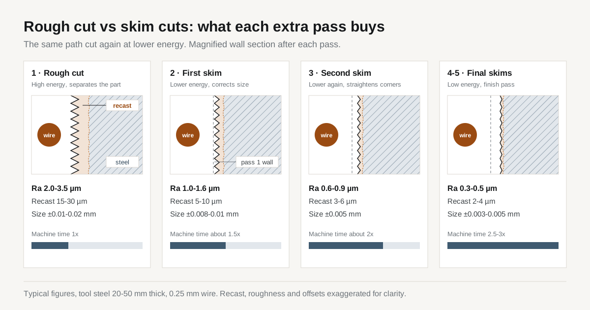
Most precision wire jobs cut the same path 2-5 times. The first pass is the rough cut: high energy, fastest, rough surface and thick recast. Size after the rough cut is typically ±0.01-0.02 mm.
The following passes are skim cuts. Each runs at lower energy and a smaller offset. Each removes a few µm up to a few hundredths of a mm.
| Passes | Size tolerance (typical) | Ra (typical) | Recast layer | Relative time |
|---|---|---|---|---|
| 1 (rough only) | ±0.01-0.02 mm | 2.0-3.5 µm | 15-30 µm | 1x |
| 2 (rough + 1 skim) | ±0.008-0.01 mm | 1.0-1.6 µm | 5-10 µm | About 1.5x |
| 3 | ±0.005 mm | 0.6-0.9 µm | 3-6 µm | About 2x |
| 4-5 | ±0.003-0.005 mm | 0.3-0.5 µm | 2-4 µm | 2.5-3x |
The figures apply to tool steel 20-50 mm thick. Best case on a temperature-controlled machine is about ±0.002 mm on short profiles. Very thin parts, very thick parts, poor flushing and long profiles widen the ranges, so confirm per drawing.
Below about Ra 0.3 µm, profiles are normally finished by stoning or lapping rather than by more passes.
Corner accuracy and wire lag
During the rough cut, spark pressure bows the wire backwards between the guides. The wire trails the guides and cuts corners short. Low-energy skim cuts straighten the wire and restore the programmed corner.
Cutting speed
- Rough cut in tool steel | 10-30 mm² per minute (profile length x part height), as a planning figure
- Example | 25 mm thick die opening, 200 mm profile = 5,000 mm² = about 3-8 hours of rough cutting
- Skim cuts | added on top, see the relative time column above
Recast layer and heat-affected zone
Molten steel that is not flushed away re-solidifies on the cut face as a recast layer, also called white layer. Below it sits a heat-affected zone, re-hardened in places and over-tempered in others. The recast layer is brittle, carries tensile stress and can hold micro-cracks after a rough cut.
On a punch or die edge loaded millions of times, cracks start in this layer. The controls are:
- Skim cuts. Low energy reduces the layer to about 2-5 µm.
- Stress-relief temper. Typically 10-25 °C below the last tempering temperature, so hardness is kept.
- Stoning or polishing. Removes the remaining layer on the working edge.
On stripper plates, retainer plates and non-working faces, the recast after 1 skim is normally accepted.
Long immersion in water can stain tool steel and leach the binder from carbide. Modern generators use anti-electrolysis pulse settings to limit this. For mirror-finish parts, the shop should state how it is controlled.
Residual stress and part movement in hardened blocks
A quenched and tempered block holds its residual stress in balance. Cutting a long slot or separating a punch from a plate releases part of that stress. The steel then moves.
Typical movement:
- Slots open or close.
- Long thin punches bow.
- Die openings near a plate edge go out of shape.
On a ±0.005 mm part, this movement can exceed the whole tolerance. Shops control it with 3 methods.
- Bulk removal before hardening. The opening is rough milled or drilled in the annealed state, with about 1-3 mm per side left. Route: rough machine → harden and temper → wire cut. The heat treat allowance table gives stock by part size.
- Rough cut, relax, then skim. The rough cut leaves an extra 0.1-0.3 mm per side, and the part is left to move. Route: rough cut with allowance → relax → skim cuts to size.
- Retained slug. A small uncut tab holds the slug and keeps the frame closed until the last cut. The tab is then cut or ground off.
Correct tempering also matters. For D2-type grades, a sub-zero step reduces retained austenite that keeps moving after cutting.
Start holes for closed profiles
Every closed internal profile needs the wire threaded through a start hole. In annealed steel this is a normal drilled hole. In hardened steel the hole is burned by an EDM hole drilling machine with a tubular electrode, as a separate setup.
Preferred route: drill start holes → harden and temper → wire cut. The drawing can show start holes for the soft stage, or leave their position to the shop.
Wire EDM compared with other finishing processes
| Feature | Wire EDM | Alternatives |
|---|---|---|
| Through-profile, sharp internal corners | First choice | Hard milling only with corner radii above about 0.5 mm |
| Punch and matching die opening | Same program with a changed offset; clearance held to a few µm | Profile grinding for the highest volumes |
| Blind pocket, floor, 3D surface | Not possible | Sinker EDM or hard milling |
| Large open contour, generous radii | Possible, slow | Hard milling is faster |
| Round diameters and bores | Possible for odd shapes | Hard turning or grinding |
| Flat faces, parallelism | Not suited | Surface grinding |
| Taper or die clearance angle | Yes, ±15-30° typical | Difficult in hardened steel by other methods |
Typical die-plate route: grind faces flat and parallel → jig grind or bore holes → wire cut all profiles. The full routing decision is in hard milling, grinding or wire EDM.
What to put on the drawing / RFQ
- Grade and hardness after heat treatment. State a band, such as D2 60-62 HRC, not “hardened”.
- Functional corners. Give a maximum radius where it matters, such as R0.1 max. A general note such as “internal corners R0.2 max unless stated” keeps the job on standard 0.25 mm wire.
- Tolerance and finish per profile. Example: die opening ±0.005 mm and Ra 0.4 µm, stripper hole ±0.02 mm. This costs less than both profiles at the tight figure.
- Recast layer. State whether it must be removed on working edges and whether a stress-relief temper follows EDM.
- Die clearance and land. Give the straight land height and the angular relief below it. Or give the clearance per side.
- Heat treatment timing. Start holes and rough openings made before hardening cut lead time. They also reduce movement.
- 3D model. Send it with the drawing, so corner and taper geometry is not rebuilt from a PDF.
Common questions
Blind pockets and 3D shapes on wire EDM?
No. The wire is a straight line through the full part height, so wire EDM cuts only through-profiles and ruled surfaces. Tapers and different top and bottom profiles are possible with the U/V axes. Blind pockets, floors and blended 3D surfaces go to sinker EDM or hard milling. The shop decides the split from the 3D model, so the model should travel with the drawing.
Number of skim cuts for a die opening?
Typically 2-4 skim cuts after the rough cut, set by the shop from the drawing callouts. A tolerance of ±0.01 mm with Ra 1.6 µm usually needs 1 skim. A tolerance of ±0.005 mm with Ra 0.4-0.8 µm and a thin recast on a working edge needs 3-4. The drawing should state tolerance, finish and recast requirement rather than a pass count. The pass plan is confirmed per part in the quote.
Slot closing after wire cutting?
Yes, a slot in a hardened block can close or open after cutting. Quenching leaves residual stress in the block, and the cut releases part of it. Movement grows with slot length and thin sections and can exceed a ±0.005 mm tolerance. Shops control it by removing bulk before hardening. The other method is a rough cut with 0.1-0.3 mm allowance, a pause for the part to relax, then skim cuts to size.
Start holes before or after hardening?
Before hardening, where the design allows it. A start hole in annealed steel is a normal drilling operation. After hardening, each start hole is burned with an EDM hole drilling machine, which adds a setup and queue time. The drawing can show start holes for the soft stage, or allow the shop to place them. Position is free as long as the hole sits inside the waste slug.
Recast layer on wire-cut punches?
Yes, on punches and cutting edges the recast layer should be reduced or removed. The layer is brittle, carries tensile stress and can hold micro-cracks after a rough cut. Skim cuts reduce it to 2-5 µm. A stress-relief temper and light stoning remove the rest. On stripper plates and non-working faces, the layer left after 1 skim is normally accepted. The drawing should mark the working edges.