Machining process
Sinker EDM
A shaped electrode is fed into a hardened block under dielectric oil, and sparks erode a mirror image of it. Sinker EDM makes features a cutter cannot reach: deep narrow ribs, sharp corners in blind pockets and spark-textured mould surfaces.
| Principle | Spark erosion between a shaped electrode and the part, submerged in dielectric oil; no contact |
|---|---|
| Hardness | Not a factor; 30 or 62 HRC burn at about the same rate. The part must conduct electricity |
| Electrodes | Graphite for most mould work; copper for fine finish; copper-tungsten for carbide and thin detail |
| Electrode undersize | 0.25-0.50 mm per side roughing; 0.05-0.15 mm per side finishing |
| Tolerance | ±0.01-0.02 mm typical on depth and width; about ±0.005 mm best case with a sizing electrode |
| Internal corner radius | About R0.1 mm in production; R0.05 mm best case with a fresh finishing electrode |
| Surface finish | Ra 3-6 µm roughing; Ra 0.4-0.8 µm fine burn (VDI 12-18); textures VDI 24-36 |
| Recast layer | A few µm after a fine burn; 30 µm or more after roughing |
| Electrode wear | Under 1% by volume on low-wear roughing settings; much higher at sharp corners and in finishing |
| Typical features | Mould cavities and ribs, die-casting and forging dies, blind hex and spline sockets, engraved text |
Sinker EDM principle
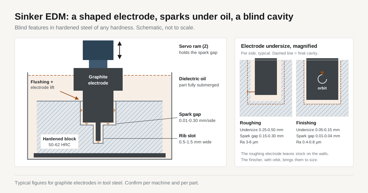
Sinker EDM, also called ram EDM or die-sinking EDM, uses a shaped electrode instead of a wire. The electrode is a positive of the feature. It sits on a ram and is fed towards the hardened part under a bath of dielectric oil.
A servo holds the electrode a few hundredths of a mm from the steel. Thousands of sparks per second jump that gap. Each spark melts a small crater in the steel and a smaller one in the electrode.
The cavity grows into a mirror image of the electrode, larger by the spark gap. The physics is the same as in wire EDM. The general principle is on the electrical discharge machining page.
The energy is thermal, so hardness has no effect on the rate. An H13 die insert at 50 HRC burns at about the same rate as annealed H13. The cavity is therefore burned after heat treatment, once the block has stopped moving.
The sinker needs no through-hole. It makes blind features:
- pockets with floors, ribs and bosses
- 3D cavity shapes and engraved text
- blind hex sockets and internal splines
Electrode materials
| Electrode | Typical use | Strengths | Limits |
|---|---|---|---|
| Graphite (fine or ultra-fine grain) | Most mould and die cavities | Fast to machine, no burrs, low wear in roughing, low cost on large electrodes | Machining dust; fine detail needs ultra-fine grades; thin ribs can chip |
| Electrolytic copper | Fine finishes, small precise features | Stable burning and good finish in finishing | Slower to machine, burrs, heavier; more wear than graphite in roughing |
| Copper-tungsten | Carbide parts, very thin ribs, sharp detail | Lowest wear, holds thin sections and corners | High cost, hard to machine |
The electrode is a machined part in its own right. Graphite and copper are milled; copper-tungsten is ground or wire cut. Each electrode is measured and mounted on a reference holder, so it locates on the machine to a few µm.
On a mould cavity, electrode making is often a large share of the EDM cost. The electrode count is therefore a main line in the quote.
Electrode undersize, spark gap and orbiting
The electrode is made smaller than the finished cavity by a fixed amount per side, the undersize. The undersize covers the spark gap of the burn plus any orbit.
| Stage | Spark gap per side (typical) | Electrode undersize per side (typical) | Ra after the stage |
|---|---|---|---|
| Roughing | 0.15-0.30 mm | 0.25-0.50 mm | 3-6 µm |
| Semi-finishing | 0.05-0.10 mm | 0.10-0.20 mm | 1.2-2 µm |
| Finishing | 0.01-0.04 mm | 0.05-0.15 mm | 0.4-0.8 µm |
These are planning figures. Each shop works from its own settings tables, so confirm per machine and per part.
Orbiting, also called planetary motion, moves the electrode sideways in a small path while it advances. The path can be a circle, a square or a programmed vector. Orbiting brings 3 effects:
- Finishing range. 1 electrode takes the walls through several finishing steps.
- Side finish. The walls get an even finish.
- Flushing. The gap opens on one side as the electrode moves.
A circular orbit adds its own radius to every vertical internal corner of the cavity. For sharp corners, the shop uses a square or vector orbit, or a separate finishing electrode with no orbit.
Electrode sets and wear
Each spark also erodes the electrode. On graphite with low-wear roughing settings, volume wear can stay under 1% of the steel removed. Finishing settings wear the electrode much faster.
Sharp corners and edges wear first, because sparks concentrate there. A worn finishing electrode leaves rounder corners and a shallower floor than the model shows.
The standard electrode set per feature:
- Roughing electrode. Removes the bulk left after milling.
- Semi-finishing electrode. Used on deep features.
- Finishing electrodes. 1 or more, measured between burns and replaced by a duplicate when worn past the limit.
Multi-cavity tools get a fresh finisher per cavity when the cavities must match.
Electrode roughing is the slowest way to remove bulk steel. Preferred route: rough mill annealed, leaving 0.2-0.5 mm per side → harden and temper → burn the remaining stock and features. The stock must still cover distortion, see the heat treat allowance table.
Surface finish and VDI 3400 textures
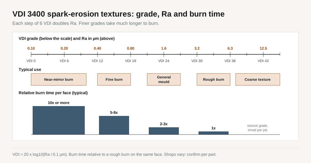
Sinker EDM leaves a matte, non-directional surface of overlapping craters. On moulds this surface is often the finished texture. It is specified on the VDI 3400 scale rather than as Ra.
| VDI 3400 | Ra (µm) | Typical use |
|---|---|---|
| 12 | 0.40 | Fine burn before polishing, sealing faces |
| 18 | 0.80 | Fine matte, technical parts |
| 24 | 1.6 | Common matte finish on housings |
| 30 | 3.2 | Visible matte texture |
| 36 | 6.3 | Coarse texture, grip surfaces |
Conversion: VDI = 20 x log10(Ra / 0.1 µm). Below about VDI 12, burn time per step climbs steeply.
A mirror finish is a polishing job, not an EDM one. It is covered under lapping, honing and polishing. Moulders check the texture against a physical comparison plate, since the same Ra looks different on different steels and plastics.
Recast layer and polishing
Sinker EDM leaves a recast layer, also called white layer, of re-solidified steel over a heat-affected zone. It runs from a few µm after a fine burn to 30 µm or more after roughing. The layer is brittle, carries tensile stress and can hold micro-cracks after heavy roughing.
| Part type | Recast treatment |
|---|---|
| Polished mould | Removed by the first polishing stones. A fine finish burn before polishing avoids pits and orange peel |
| Die-casting and forging dies | Removed on working faces, then stress relieved. Recast is an early start point for heat checking |
| Cold-work punches and forming tools | Removed on working faces. Stress-relief temper 10-25 °C below the last tempering temperature |
Achievable tolerances and feature limits
- Depth and width | ±0.01-0.02 mm typical; about ±0.005 mm best case with a sizing electrode and a re-measure step
- Position | set by electrode location and measurement; a common electrode datum for cavities that must match
- Internal corners | about R0.1 mm in production; R0.05 mm best case with a fresh fine-grain or copper finisher and no circular orbit
- Rib slots | 0.5-1.5 mm wide at depths many times the width, with slow burning, frequent electrode lifts and several electrodes per rib
- Finish | Ra 0.4-0.8 µm (VDI 12-18) in normal production; finer grades with much longer burn times
All figures depend on feature size and depth, so confirm per drawing.
Sinker EDM compared with hard milling
Hard milling with small carbide or CBN end mills now takes much of the cavity work that used to be burned. It needs no electrodes and leaves no recast layer. The deciding factor is which features a cutter can reach.
| Feature | Points to hard milling | Points to sinker EDM |
|---|---|---|
| Internal corner radius | 0.5 mm or more | Below about 0.3 mm |
| Rib slot | Width 1.5 mm or more, depth under about 6-10 x the cutter diameter | Narrow and deep |
| Shape | Open cavity, blended 3D surfaces | Blind sharp pockets, square bottoms, engraved text |
| Surface | Polished or machined finish | Spark texture (VDI) specified |
| Material | Up to about 60-62 HRC | Any hardness, carbide included |
| Lead time | No electrodes to make | Electrodes add design and machining time |
The common route on a hardened mould insert is hybrid: hard mill all reachable surfaces → burn the remaining ribs and corners. Through-profiles go to wire EDM. Round bores and seats go to hard turning or grinding.
The longer routing discussion is in hard milling, grinding or wire EDM.
What to put on the drawing / RFQ
- Grade and hardness after heat treatment. State a band, such as H13 46-50 HRC.
- Finish per face. Use VDI where a texture is wanted and Ra elsewhere. Mark faces that will be polished, so the shop burns them fine enough.
- Corner radii. Give a maximum radius where the corner is functional and allow a larger one elsewhere. R0.05 max and R0.3 max are very different jobs.
- Recast layer. Note “remove on working faces” and the stress-relief temper for fatigue- or impact-loaded parts.
- Datums for multi-cavity tools. State whether the electrodes must share one datum.
- Electrodes and model. Note whether electrodes are supplied by the toolmaker, and send the 3D cavity model with the drawing.
Common questions
Burning the cavity before heat treatment?
Not recommended for finished cavities. Heat treatment moves the burned shape and leaves scale or decarburisation on the faces. Standard route: rough mill annealed → harden and temper → grind datums → burn to final size. EDM removes hardened steel at about the same rate as annealed steel, so burning after hardening adds no time. Exceptions, such as roughing burns on large dies, are decided per part.
Meaning of VDI 24 on a mould drawing?
VDI 24 is a spark-eroded texture of about Ra 1.6 µm on the VDI 3400 scale. The grade equals 20 x log10 of Ra in units of 0.1 µm, so VDI 30 is about Ra 3.2 µm. Moulders specify it so the cavity leaves the EDM machine with its final matte texture. The texture is checked against a comparison plate, since appearance varies with steel and plastic.
Number of electrodes per cavity?
Typically 2-4 electrodes per feature. A simple pocket can use 1 roughing and 1 finishing electrode, with orbiting to finish the walls. Deep ribs, sharp corners and tight tolerances usually need a roughing, a semi-finishing and 1-2 finishing electrodes. Multi-cavity tools add duplicate finishers, so each cavity is burned with a fresh corner. The shop sets the count from the 3D model and states it in the quote.
Recast layer removal after sinker EDM?
Yes on the working faces of dies and punches; polished moulds usually need no extra step. Polishing removes the layer with the first stones. On die-casting dies, forging dies and cold-work punches, the brittle layer is a crack start and should be removed. A stress-relief temper 10-25 °C below the last tempering temperature follows EDM. The drawing should mark the faces concerned.
Sinker EDM speed compared with hard milling?
Sinker EDM is usually several times slower on open cavities. Electrodes also need design and machining before the burn starts. Hard milling is faster on open shapes with corner radii of 0.5 mm or more. Sinker EDM is chosen for narrow deep ribs, sharp blind corners below about 0.3 mm and specified VDI textures. Most hardened mould inserts use both: mill first, then burn the remaining features.