Hardened injection mold inserts: cores, cavities and slides
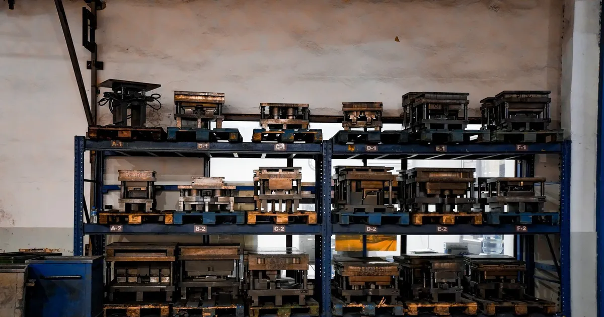
An injection mold is mostly a steel base with a few small, hard, precise parts inside it. Those parts, the cavity inserts, the cores, the slides and the lifters, are where the plastic touches steel, and they are the pieces that wear, crack or flash. They are also the parts most often sourced as separate hardened components.
This note covers what each insert does, which steel and hardness fit it and the specification points that decide whether the insert works in the mold.
What each insert does
- Cavity insert forms the outside of the plastic part. It carries the surface finish, texture and parting line.
- Core insert forms the inside of the part. It stands in the middle of the flow and often carries ribs, bosses and deep pockets.
- Slide moves sideways to form undercuts and side holes, and runs against a guide.
- Lifter moves at an angle during ejection to release internal undercuts.
- Core pin and sleeve make holes and thin features. They are small, long and usually the first to wear or bend.
Each sees a different load. Cavities see pressure and gloss demands. Cores see heat, push-off force and wear at the base. Slides and lifters see sliding wear and side load.
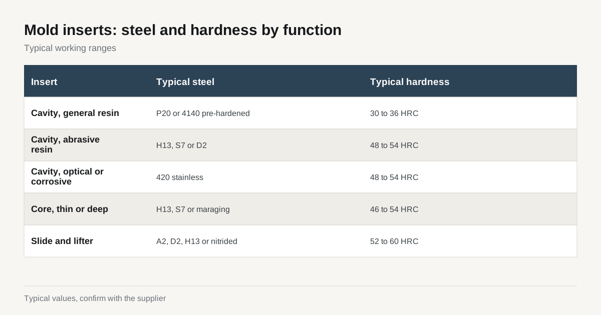
Steel and hardness by function
| Insert | Typical steels | Typical hardness | Why |
|---|---|---|---|
| Cavity, general resin | P20 or 4140 pre-hardened | 30 to 36 HRC | Easy to machine, no heat treat distortion |
| Cavity, high volume or abrasive resin | H13, S7 or D2 | 48 to 54 HRC | Wear resistance with glass-filled resins |
| Cavity, optical or corrosive resin | 420 stainless | 48 to 54 HRC | Polish and corrosion resistance |
| Core, thin or deep | H13, S7 or maraging | 46 to 54 HRC | Strength to resist bending and cracks |
| Slide and lifter | A2, D2, H13 or nitrided pre-hard | 52 to 60 HRC | Sliding wear resistance |
| Core pin | M2, H13 or carbide | 55 to 62 HRC | Small diameter, wear and bend |
Our notes on 420 stainless mold steel and pre-hardened and through-hardened tool steel explain the main trade-offs for cavities.
The pre-hardened route and its limits
P20 and 4140 supplied at 30 to 36 HRC are the default for prototype and low to medium volume molds. They machine directly to final size and need no heat treatment, so there is no distortion. The cost is lower wear resistance. A P20 cavity running unfilled polypropylene for 200,000 shots will do fine. The same cavity running 30 percent glass-filled nylon may show wear at the gate in tens of thousands.
Moving to a through hardened steel such as H13 at 50 HRC brings better wear resistance but adds the heat treatment step and the finishing steps after it. That affects cost and lead time.
Making a hardened insert
A typical route for a through-hardened cavity insert:
- Rough machine from annealed block, leaving 0.3 to 0.5 mm on all surfaces.
- Stress relieve.
- Heat treat to the target hardness, with a vacuum cycle for dimensional control.
- Grind the outside faces and fit surfaces square and to size.
- Finish the cavity by hard milling and sinker EDM for deep or sharp features. Our article on sinker EDM for hardened mold cavities covers this step.
- Stress relieve after EDM.
- Polish or texture the cavity face.
- Inspect size, fit and hardness.
The outside fit of an insert in its pocket is usually a close sliding fit, for example H6 or H7 on the pocket and a matching tolerance on the insert, with a typical clearance of 0.005 to 0.015 mm. Too tight and the insert will not seat, too loose and plastic flashes into the gap or the insert moves under pressure.
Vents, parting lines and tolerances
Plastic flows into every gap it can find. Parting line faces are normally ground flat and parallel to 0.005 mm or better so the two mold halves close with no gap. Vents let air escape from the cavity as it fills. Standard vent depth is 0.015 to 0.04 mm for most thermoplastics, depending on resin viscosity. A vent that is too deep flashes, and one too shallow burns the plastic from trapped air.
Ejector pin holes, core pin holes and slide guides are finished to close fits. Position matters: a core pin that sits off position by 0.02 mm shows up as wall thickness variation in the moulded part. Mark datum features and the tolerance chain clearly.
Slides and lifters
Slides run on a guide surface, usually with a wear plate. The sliding surfaces need hardness and a smooth finish, commonly Ra 0.4 µm or better, and they work best when the two sliding parts have different hardness or different surface treatment to reduce galling. A common pairing is hardened steel against nitrided steel or against bronze wear plates.
Lifters rely on thin sections and angled motion. They are usually machined from a tough, hard steel such as H13 or maraging steel and then nitrided. See our note on nitriding and PVD after hard machining for the sequence and stock.
Heat treatment distortion on inserts
Small inserts distort less than large plates, but thin walls and asymmetric shapes still move. If the insert holds a long slender core, plan a straightening step or a stock allowance. For critical fits, grind the outside after heat treatment. The reference table for heat treat allowance gives guide figures for stock, and the grade matters: A2 and H13 distort less than D2 and O1.
Cooling and why inserts carry channels
Mold temperature controls cycle time and part quality, and cooling channels often run through inserts. A core that stands in the middle of a hot part cannot lose heat to the mold base, so it needs its own cooling: a bubbler, a baffle or a conformal channel. Channels must be sealed with O-rings or plugs and tested for leaks at pressure before the mold goes into the press.
Cooling holes weaken the insert and sit close to the cavity wall, usually 1.5 to 2 diameters from the surface. If they are drilled after hardening, that is gun drilling or EDM drilling, both slow and costly. Drilling them before hardening risks distortion and hole movement. Decide on the cooling layout early, because it affects the process route and the steel choice. Maraging steel with printed conformal channels is an option for complex shapes. See our note on maraging steel 18Ni300 for what that route involves.
Wear points to watch
Four places on an insert wear first. The gate area takes the highest shear and erodes first, especially with glass-filled resins. The shutoff faces, where slides and cores close against the cavity, wear and flash. The tips of thin core pins bend or wear. And vents clog and erode. Specify harder steel, surface treatment or replaceable gate inserts at these points instead of hardening the entire insert more.
Replaceable inserts at wear points are a practical design choice. A small gate insert in D2 or carbide in a P20 cavity can be swapped in minutes, and the rest of the mold keeps running. Ask the mold designer whether wear parts have been planned for, and order spares when the tool is built.
Replacement inserts for an existing mold
Many orders are for a worn or damaged insert in a mold that already runs. Here the original dimension and fit rule over the model. Ask for a sample of the old insert or a measured drawing, since the pocket may have worn or been reworked, and an insert made to the original model may not fit. Give the shop the steel, hardness and surface finish of the old part, plus what went wrong with it, so the replacement can fix the weak point instead of repeating it.
Lead time depends on whether the steel is stocked, so confirm the grade early. A replacement made from a different steel than the rest of the mold can polish or wear differently and show up as a visible mark on the part.
What to put on the drawing
- Steel grade and hardness for each insert
- Surface finish per face: polish grade, texture or burned finish
- Fit tolerances on the outside and on all pin and bushing bores
- Parting line flatness and datum scheme
- Vent locations and depths
- Resin to be moulded, so the shop can sanity check hardness and polish
- Stress relief after EDM and any surface treatment
Checklist before you send the RFQ
- 3D model and 2D drawing with the insert tolerances.
- Resin, expected shots and required surface.
- Whether inserts are replacements for an existing mold, with the original steel and hardness if known.
- Number of cavities and spares.
- Delivery format: finished, or semi-finished for the mold maker to fit.
Send the drawing through the RFQ form and a written quote comes back within 24 business hours.