Machining process
Grinding
Grinding removes hardened steel with an abrasive wheel, a few microns per pass. It holds the tightest size, flatness and roundness of any cutting process on 58-65 HRC parts. It is also the step where poor practice can burn or crack a correctly heat-treated part.
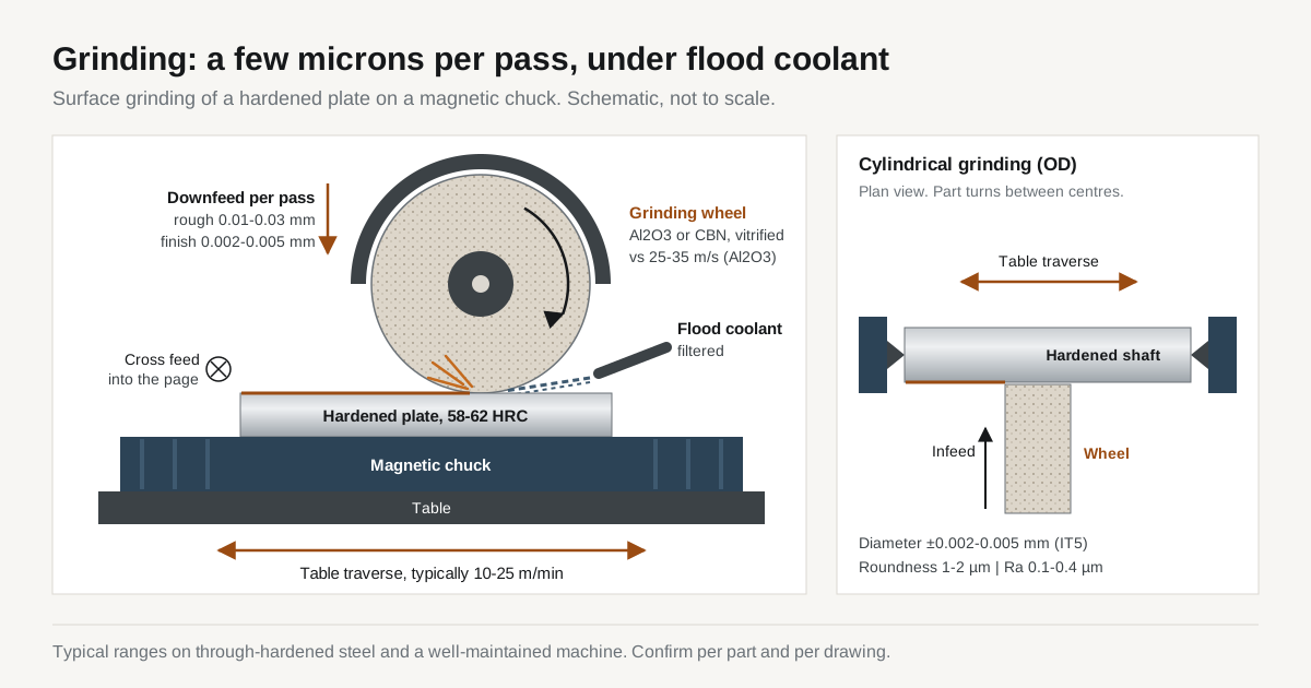
| Hardness range | Any hardened steel; routine at 58-65 HRC |
|---|---|
| Wheels | Vitrified aluminium oxide for most tool steels; CBN for high-vanadium and high-speed steels |
| Wheel speed | Aluminium oxide 25-35 m/s; vitrified CBN typically 30-60 m/s |
| Downfeed | Roughing 0.01-0.03 mm per pass; finishing 0.002-0.005 mm, then spark-out |
| Size tolerance | Typical ±0.005 mm; best case ±0.002 mm; confirm per drawing |
| Flatness | 0.002-0.005 mm per 100 mm on a stiff plate |
| Roundness | 1-2 µm typical, below 1 µm best case (cylindrical and centerless) |
| Surface finish | Ra 0.1-0.4 µm cylindrical; Ra 0.2-0.8 µm surface grinding |
| Coolant | Flood, filtered; always used |
| Grinding stock | 0.1-0.3 mm per side after heat treatment, by size and distortion |
Grinding on hardened steel: role and sequence
Grinding cuts with thousands of small abrasive grains bonded into a wheel. Each grain removes a chip a few microns thick, so the process is indifferent to workpiece hardness. On hardened steel it is the final sizing step for faces, diameters, bores and profiles.
The usual sequence is rough machine → harden and temper → grind. The part arrives with 0.1-0.3 mm per side of grinding stock. The heat treat allowance table lists typical stock by part size.
Grinding always runs with flood coolant. Hard turning runs dry because it needs heat in the shear zone. Grinding needs the opposite, because heat at the grinding contact damages the surface.
Grinding types and what each holds
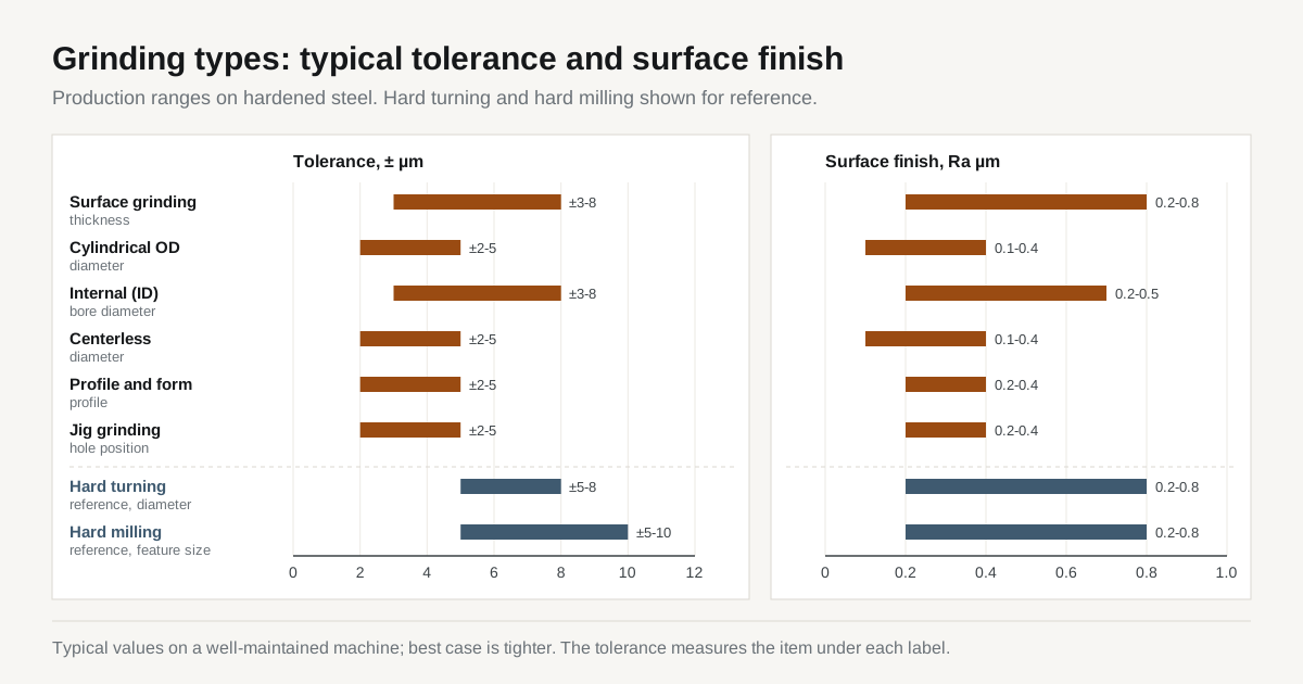
| Type | Typical parts | Size or position | Geometry | Ra |
|---|---|---|---|---|
| Surface | Plates, die blocks, gauge blocks, punch heads | ±0.005 mm thickness, ±0.002 mm best case | Flatness 0.002-0.005 mm per 100 mm; parallelism 0.003-0.005 mm | 0.2-0.8 µm |
| Cylindrical OD | Shafts, pins, punches, bearing seats | ±0.002-0.005 mm diameter | Roundness 1-2 µm | 0.1-0.4 µm |
| Internal (ID) | Bushings, die buttons, bores | ±0.003-0.008 mm | Roundness 1-3 µm | 0.2-0.5 µm |
| Centerless | Pins, ejector pins, rollers, plain shafts | ±0.002-0.005 mm | Roundness 0.5-2 µm | 0.1-0.4 µm |
| Profile and form | Punch profiles, form tools, guide rails | ±0.002-0.005 mm on profile | Inside corner radius down to about 0.05-0.1 mm | 0.2-0.4 µm |
| Jig | Dowel holes, guide bores, die openings | ±0.002-0.005 mm hole position | Roundness 2 µm or better | 0.2-0.4 µm |
Typical production values on a well-maintained machine. Confirm per part and per drawing.
Surface grinding
The part sits on a magnetic chuck and the table reciprocates under the wheel. The wheel cross-feeds a fraction of its width per stroke and downfeeds at each pass.
Surface grinding sets thickness, flatness and parallelism on plates and blocks. Details on plates are in the blog post on surface grinding hardened plates.
Cylindrical grinding (OD and ID)
The part turns between centres or in a chuck while the wheel infeeds against it. OD grinding holds IT5 on diameters, about ±0.004 mm on a 30 mm shaft.
ID grinding uses a small wheel on a long quill. Quill deflection limits ID work to slightly wider tolerances than OD work.
Centerless grinding
The part runs on a work rest blade between a grinding wheel and a regulating wheel, with no centres. Through-feed grinds plain pins continuously; in-feed (plunge) grinds parts with shoulders.
Centerless grinding can produce odd-lobed out-of-roundness that a 2-point micrometer does not detect. Roundness on centerless parts is checked on a roundness tester or in a V-block.
Profile and form grinding
Profile grinding uses a wheel dressed to the required shape or a small wheel following a CNC path. Typical parts are punch profiles, form tools and rails.
Optical profile grinders compare the part to a magnified drawing during the cut. Outside corners can be sharp; inside corners are limited by the dressed wheel radius.
Jig grinding
A small high-speed spindle orbits inside a hole while the machine positions it in X and Y. Jig grinding finishes holes to a few microns of position and roundness. The blog post on jig grinding hardened die plates covers when hole tolerances justify it.
Grinding wheels and dressing
| Abrasive | Bond | Application |
|---|---|---|
| White or pink aluminium oxide | Vitrified | General tool steels up to about 62 HRC: O1, A2, S7, H13, 4140, 52100 |
| Ceramic (sintered) aluminium oxide | Vitrified | Higher stock removal, tougher grades, lower burn risk than standard oxide |
| CBN | Vitrified | High-vanadium and high-speed steels: M2, M42, powder steels; long production runs |
| CBN | Resin | Tool and cutter grinding, some profile work; needs separate truing and sharpening |
| Diamond | Any | Not used on steel. Carbon diffuses into iron at grinding temperature and the grain wears quickly |
Vanadium carbides are harder than aluminium oxide grain. On high-vanadium grades an oxide wheel dulls fast and generates heat. CBN wheels cut these grades cooler and hold their form longer.
Wheel grade rule for hard steel: a softer bond. Dull grains must break out before they rub. A wheel too hard for the job glazes and burns the part.
Dressing restores sharp grains and the wheel’s shape:
- Single-point or multi-point diamond | standard for vitrified aluminium oxide wheels
- Rotary diamond disc or roll | form dressing and vitrified CBN
- Coarse dress | freer cutting and less heat, rougher finish
- Fine dress | finer finish, more heat; used for the last passes only
Grinding burn and grinding cracks
Grinding burn is thermal damage at the ground surface. It occurs in 2 forms:
| Type | Cause | Result |
|---|---|---|
| Temper burn | Surface heated above the tempering temperature | Softer over-tempered layer, lower wear resistance |
| Re-hardening burn | Surface heated above the austenitising temperature, then quenched by coolant | Brittle untempered martensite over a soft zone; tensile residual stress |
Grinding cracks usually start in burned areas. They are fine cracks, often at right angles to the grinding direction or in a network pattern. They may open later in service under load.
Common causes:
- Dull or loaded wheel, or a wheel grade too hard for the steel
- Downfeed too large on the final passes
- Coolant not reaching the contact zone
- Parts with high retained austenite, for example D2 or carburised parts without a full temper cycle
Discolouration is a warning sign, but its absence proves nothing; coolant can hide it. Inspection methods:
- Nital temper etch | shows temper and re-hardening burn
- Magnetic particle or dye penetrant | shows cracks
- Barkhausen noise | non-destructive burn check, see Barkhausen effect
Magnetic chuck and demagnetising
The magnetic chuck holds steel parts without clamps. On thin plates it also pulls the part flat. A plate with heat-treat bow is ground flat while clamped, then springs back after release.
Shop methods for thin plates:
- Grinding both sides alternately, with several flips
- Reduced chuck force on finishing passes
- Shims under the gap of a bowed plate
- Vacuum or mechanical clamping for very thin parts
- Stress relief between roughing and finishing, where the grade allows
Parts leave the chuck with residual magnetism. It holds swarf on sliding faces, bearing seats and gauge surfaces. Demagnetising after grinding is a separate step; the drawing states it with a measurable limit.
Cases where grinding is required
- Size below ±0.005 mm | or IT5 and finer on diameters
- Roundness below 2 µm | cylindricity on bearing and seal seats
- Flatness or parallelism of a few microns | over large plates and die blocks
- Ra below 0.2 µm | on functional surfaces, before lapping
- Long slender shafts | length to diameter above about 6-8:1, beyond the reach of hard turning
- Hole position ±0.005 mm or tighter | jig grinding
- “Ground” called out on the drawing | some aerospace and automotive standards name the process
Above these limits, hard milling and hard turning usually cost less. Below Ra 0.1 µm or for flatness in the sub-micron range, lapping and polishing follow grinding.
Grinding vs other finishing routes
| Feature | Grinding | Hard turning | Hard milling | Wire EDM |
|---|---|---|---|---|
| Flat face to 0.005 mm | First choice | Faces only on round parts | Marginal over large areas | Not applicable |
| Diameter IT5 | First choice | IT6 typical | Not applicable | Not applicable |
| 3D cavity | Not applicable | Not applicable | First choice | Not applicable |
| Sharp inside corner, through profile | Not possible | Not applicable | Limited by tool radius | First choice |
| Surface layer | Clean if burn-free | Clean with fresh edge | Clean | Recast layer |
| Setups | 1 per face or diameter | 1 for several features | 1-2 | 1 |
Through profiles with sharp inside corners go to wire EDM. A common route: hard mill or hard turn most features → grind the 2-3 critical faces.
Drawing and RFQ requirements
- Hardness | as a band after heat treatment, e.g. 58-62 HRC.
- Grade | by standard designation. D2 and M2 change wheel choice and cycle time.
- Ground surfaces | mark each surface that must be ground. Leave the rest to the shop’s routing.
- Geometric tolerances per surface | flatness, parallelism, roundness or position, each on the feature that needs it.
- Finish per surface | e.g. Ra 0.2 µm on a bearing seat and Ra 0.8 µm on other faces.
- Burn and crack inspection | method and sample size, e.g. nital etch per batch, for fatigue-loaded parts.
- Demagnetising | required or not, with a residual field limit.
- Grinding stock | if the shop receives a pre-machined blank, the stock left per side.
Common questions
Grinding vs hard milling or hard turning?
Grinding is required below about ±0.005 mm or 2 µm roundness. It is also required for flatness of a few microns over a large face. Above those limits, hard turning covers most round parts and hard milling covers most prismatic parts. The decision is made per feature, not per part. A common plan grinds only the 2 or 3 faces that carry the tight callout and machines the rest.
Grinding burn: definition and inspection?
Burn is thermal damage from grinding heat. Temper burn leaves a softer, over-tempered layer. Re-hardening burn leaves brittle, untempered martensite with tensile stress. Neither is reliably visible to the eye. Inspection uses a nital temper etch on the ground surface or Barkhausen noise testing. Cracks are checked by magnetic particle or dye penetrant inspection. The drawing or purchase order states which method applies.
Residual magnetism after surface grinding?
Yes, parts held on a magnetic chuck keep some magnetism unless they are demagnetised. Residual magnetism holds chips and grinding swarf on the part. It is a problem on bearings, gauges, mould components and sliding parts. A drawing note makes the requirement checkable: "demagnetise after grinding" plus a limit. An example limit is 0.3 mT (3 gauss), measured with a field indicator.
Flatness loss on thin ground plates?
Thin plates often lose flatness after leaving the chuck. The magnet pulls a bowed plate flat, the wheel grinds it flat while clamped, then the bow springs back on release. Grinding also removes a stressed surface layer, which can add bow. Shops counter this with alternate grinding of both sides, reduced chuck force, shimming and stress relief. Flatness on thin plates is confirmed per drawing.
CBN vs aluminium oxide wheels?
For most tool steels the wheel is the shop's choice and does not change the finished part. Vitrified aluminium oxide is standard on low-alloy and medium-carbide grades. CBN is preferred on high-vanadium grades such as M2 and powder steels, because their carbides are harder than aluminium oxide grain. CBN runs cooler and holds wheel form longer, which lowers burn risk. The quote may differ because CBN wheels cost more.
Grinding stock to leave before heat treatment?
Typically 0.1-0.3 mm per side, set by part size and expected distortion. Small, compact parts in air-hardening grades need the least stock. Long, thin or asymmetric parts in oil- or water-quenched grades need the most. Too little stock leaves soft or decarburised skin. Too much stock costs grinding time and raises burn risk. The heat treat allowance table lists typical values by part size.