Machining process
Hard milling
Hard milling finishes steel after heat treatment on a machining centre. Coated carbide or CBN end mills take light, fast cuts on mould cavities, die inserts and punches. On many cavities it replaces the electrode and sinker EDM route.
| Hardness range | 45-65 HRC; most work at 48-62 HRC |
|---|---|
| Tools | Coated carbide ball-nose, bull-nose and high-feed end mills; CBN ball-nose for small finishing tools above about 58 HRC |
| Cutting speed | Coated carbide about 60-200 m/min, lower as hardness rises |
| Radial engagement | Roughing 3-8% of tool diameter (trochoidal); finishing stepover 0.05-0.3 mm |
| Finishing stock | 0.05-0.10 mm, left even by a semi-finish pass |
| Tolerance | Typical ±0.01 mm; best case ±0.005 mm on called features; confirm per drawing |
| 3D profile | 0.01-0.02 mm on freeform cavity surfaces |
| Surface finish | Typical Ra 0.4-0.8 µm; best case Ra 0.2 µm on small areas |
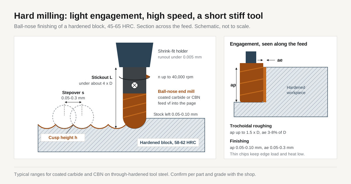
| Setup | Shrink-fit or hydraulic holder, runout under 0.005 mm, stickout under about 4×D |
| Coolant | Usually dry, air blast or MQL |
Definition and typical parts
Hard milling is CNC milling of steel after heat treatment, typically at 48-62 HRC and up to about 65 HRC. The usual sequence is rough machine → harden and temper → hard mill to size. Heat treatment distortion is machined out in the last step.
The process became practical in the 1990s. 3 developments made it possible:
- Fine-grain carbide with heat-resistant coatings
- High-speed spindles
- CAM software that holds tool load constant
Typical parts:
- Mould cavities, cores and inserts
- Die inserts and forging dies
- Punch profiles and form tools
- Cavities that were once made with graphite or copper electrodes and sinker EDM
Cutting mechanism and machining stages
Hardened steel tolerates very little load per cutting edge before the edge chips. Hard milling uses light engagement and high cutting speed to keep the chip thin. The cutting zone heats and softens the steel locally, and the chip carries most of the heat away.
Flood coolant would quench the edge on every revolution and crack the coating. Most hard milling therefore runs dry, with an air blast or with minimum-quantity lubrication (MQL).
The work is split into stages, each with its own engagement:
| Stage | Typical tool | Engagement | Purpose |
|---|---|---|---|
| Roughing (if done hard) | Bull-nose or high-feed end mill, 6-16 mm | Trochoidal: ap up to 1.5×D, ae 3-8% of D. High-feed: ap 0.2-0.5 mm, wide ae | Remove bulk stock at constant tool load |
| Rest machining | Smaller bull-nose or ball-nose | Same chip load as roughing | Clear corners the large tool could not reach |
| Semi-finish | Ball-nose or bull-nose | ae and ap 0.1-0.3 mm | Leave an even 0.05-0.10 mm everywhere |
| Finish | Ball-nose (3D), bull-nose or flat end mill (walls, floors) | ae 0.05-0.3 mm, ap 0.05-0.10 mm | Final size and surface |
Constant-engagement toolpaths
A conventional offset toolpath raises the tool load 2-3 times at every inside corner. At 60 HRC that load spike breaks small tools.
Trochoidal and other constant-engagement paths keep the arc of contact the same along the whole path. Details are in trochoidal and dynamic toolpaths.
Rest machining and even stock
After a 10 mm tool roughs a cavity, the corners still hold material. Rest machining calculates that remaining stock and cuts only it, at the small tool’s own chip load.
The semi-finish pass leaves an even 0.05-0.10 mm for the finishing tool. Uneven stock makes the finishing tool deflect by different amounts, and the surface follows that deflection.
End mill types for hardened steel
| Tool | Application | Notes |
|---|---|---|
| Coated carbide ball-nose | 3D finishing of cavities and cores, 45-65 HRC | Fine-grain carbide with AlTiN, AlCrN or TiSiN-type coating. Most common tool |
| Coated carbide bull-nose (corner radius) | Roughing, rest machining, flat floors | Stronger corner than a sharp end mill |
| High-feed end mill | Roughing open areas | Shallow depth, high feed per tooth; force directed axially into the spindle |
| CBN ball-nose | Finishing small features above about 58 HRC | Diameters about 0.5-6 mm. Longer life, holds size over long paths. Finishing only |
| Necked long-reach ball-nose | Deep ribs and pockets | Short flute, relieved neck. Each extra diameter of reach lowers feed and finish |
Spindle speed is set on the effective diameter, not the nominal one. A 6 mm ball-nose cutting 0.1 mm deep touches the work on a circle about 1.5 mm across. The spindle must turn about 4 times faster than the nominal diameter suggests, so small tools need 20,000 rpm or more.
Tool holding sets the limit for accuracy and tool life:
- Holder | shrink-fit or hydraulic
- Runout | under 0.005 mm at the tool tip
- Stickout | as short as the geometry allows, ideally under about 4×D
Stepover and cusp height
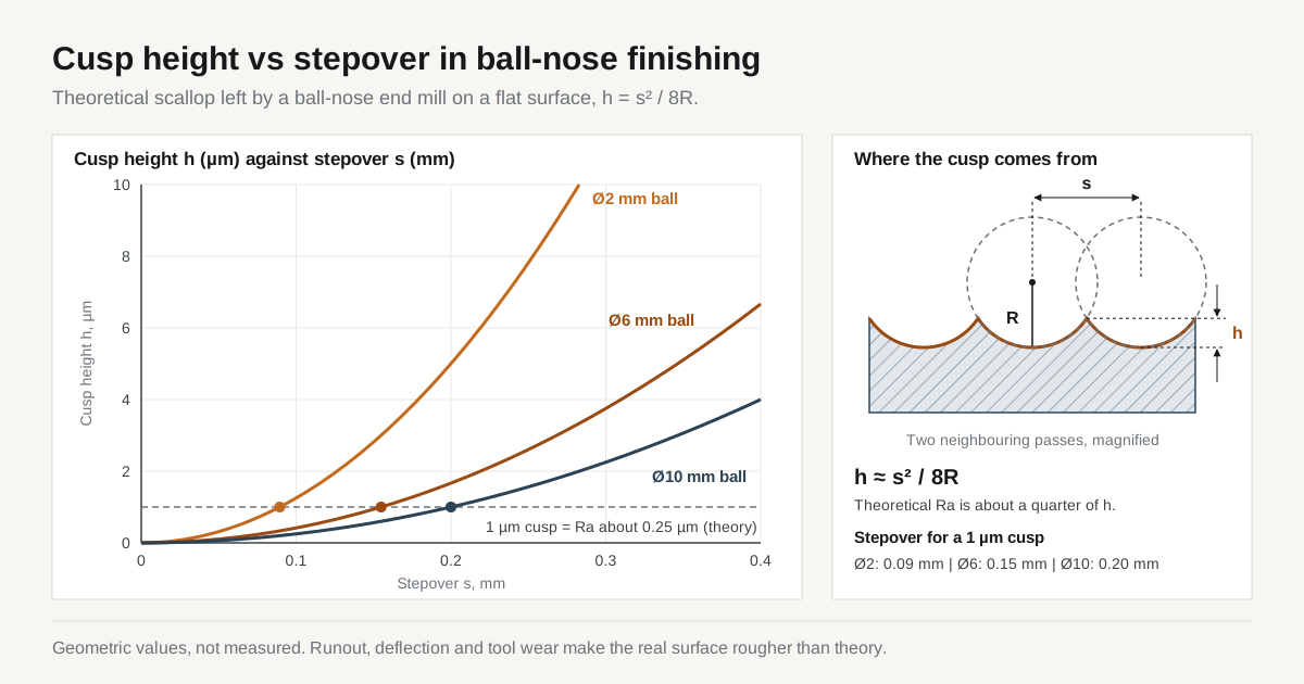
A ball-nose tool leaves a small ridge, or cusp, between neighbouring passes. Its height depends on the ball radius R and the stepover s:
h ≈ s² / 8R
| Ball diameter | Stepover 0.1 mm | Stepover 0.2 mm | Stepover 0.3 mm |
|---|---|---|---|
| 2 mm | 1.25 µm | 5.0 µm | 11.3 µm |
| 6 mm | 0.42 µm | 1.7 µm | 3.8 µm |
| 10 mm | 0.25 µm | 1.0 µm | 2.3 µm |
Halving the stepover cuts the cusp to 25% of its height and doubles the finishing time. The theoretical Ra of a cusp profile is about 25% of its height. A 1 µm cusp corresponds to roughly Ra 0.25 µm, before runout, deflection and tool wear add to it.
Shops finish with the largest ball the geometry allows. A small internal radius specified across a whole cavity forces a small ball and slows the finishing of every surface.
3-axis vs 5-axis hard milling
On a 3-axis machine the ball-nose tool stays vertical. On flat or gently sloping surfaces its centre point, where cutting speed is zero, ends up in the cut. The centre rubs instead of cutting, which degrades the finish and wears the tool tip.
A 5-axis machine tilts the tool, usually 10-20°, so the contact point moves onto the faster part of the ball. The tilt also lets a short holder reach into a deep cavity clear of the walls. Cantilever deflection grows with the cube of stickout, so halving the length reduces bending about 8 times.
| Setup | Typical use |
|---|---|
| 3-axis | Shallow open parts, flat-bottomed pockets, plates |
| 3+2 positioning (tilt, lock, mill in 3 axes) | Most cavities and inserts |
| Simultaneous 5-axis | Deep ribs, steep walls, forms where the tilt must change continuously |
Tolerances and surface finish
Figures for a warmed-up, thermally stable machining centre. Confirm per part and per drawing.
| Characteristic | Typical | Best case |
|---|---|---|
| Size | ±0.01 mm | ±0.005 mm on a few called features, with on-machine probing |
| 3D profile | 0.02 mm | 0.01 mm |
| Surface finish (Ra) | 0.4-0.8 µm | 0.2 µm on small areas with fine stepover |
| Internal corner radius | Equal to tool radius | 0.25-0.5 mm with 0.5-1 mm tools at shallow depth |
Heat and wear set these limits. The spindle grows as it warms up. A long finishing path wears the tool, so the end of the path comes out slightly oversize.
Shops manage this with warm-up cycles, by splitting long paths between tools and by using CBN on critical areas.
Below Ra 0.2 µm, bench polishing or lapping after milling usually costs less than finer milling.
Limits of hard milling
Deep, narrow features. Ribs and slots deeper than about 6-10 times their width need long tools. Those tools deflect and chatter. Sinker EDM handles these features with less risk.
Sharp internal corners. A milled corner can never be sharper than the tool radius. Through profiles with sharp inside corners go to wire EDM; blind ones go to sinker EDM.
Large flat faces to a few microns. Each pass leaves its own marks. Machine straightness also shows over 300 mm of travel. Flatness and parallelism of a few microns over a large plate belong to grinding.
Round parts. Diameters, bores and shoulders on a turned part are faster and more accurate by hard turning.
High-carbide grades at high hardness. D2 at 62 HRC and high-vanadium powder steels wear tools quickly. A large finishing surface may need several tools, each leaving a small step.
Hard milling vs sinker EDM vs grinding
| Feature | Hard milling | Sinker EDM | Grinding |
|---|---|---|---|
| Open 3D cavity or core | First choice | Only where ribs or corners require it | Not applicable |
| Rib or slot deeper than 6-10× width | Slow, high risk | First choice | Not applicable |
| Sharp internal corner | Limited by tool radius | Yes, in blind cavities | Outside corners and open profiles only |
| Flat face, flatness under 0.005 mm | Marginal | Not applicable | First choice |
| Recast layer | None | Yes, polished off on critical surfaces | None |
| Lead time | Shortest; no electrodes | Electrodes add days | Separate setup per face |
A common mould insert route: hard mill the cavity → sinker EDM 2-3 deep ribs → grind shut-off faces.
Drawing and RFQ requirements
- Hardness | as a band after heat treatment, e.g. 52-54 HRC or 58-62 HRC, not “hardened”.
- Grade | by standard designation. H13 at 48-52 HRC and D2 at 60 HRC are different jobs on the same geometry.
- Tight features | ±0.005 mm only on the features that need it; the rest at ±0.01 mm or ±0.02 mm.
- Internal corner radii | as large as the design allows. A larger radius allows a larger, stiffer tool and a wider stepover.
- Finish per surface | e.g. Ra 0.4 µm on the moulding surface and Ra 1.6 µm on clearance faces. State whether the cavity will be polished or textured.
- EDM acceptance | whether EDM is allowed on ribs and corners, and whether the recast layer must be removed.
- Blank condition | annealed for roughing first, or already hardened. Stock to leave before hardening is in the heat treat allowance table.
Common questions
Hard milling as a replacement for sinker EDM?
Yes, on most open cavities, cores and inserts. Hard milling removes electrode design, electrode machining and burn time. It also leaves no recast layer to polish off. Slots deeper than about 6-10 times their width still go to EDM. Internal corners sharper than the smallest usable tool radius also go to EDM. Many moulds end up mostly milled, with 2 or 3 EDM features.
Tolerance limit of hard milling on a hardened insert?
About ±0.01 mm across a part and ±0.005 mm on a few called features. Freeform surfaces typically hold 0.01-0.02 mm profile. The tight figures need a warmed-up machine, on-machine probing and a temperature-controlled room. Below ±0.005 mm, or for flatness of a few microns over a large face, grinding is the safer route. The achievable figure is confirmed per drawing.
Roughing before or after heat treatment?
Usually before. Roughing soft and leaving 0.2-0.5 mm per side for distortion costs less than roughing hardened steel. The usual sequence is rough machine → harden and temper → hard mill to size. Small inserts are sometimes milled entirely from a hardened blank. That avoids distortion but uses more tool life and machine time. The heat treat allowance table gives typical stock by part size.
Polishing after hard milling?
Depends on the finish class. As milled, Ra 0.4 µm is typical and Ra 0.2 µm is reachable on small areas. That is enough for many technical moulds and die faces. Optical, high-gloss and textured cavity surfaces still need bench polishing or texturing. A hard-milled surface needs less polishing time than an EDM surface, because there is no recast layer to remove.
Price difference between 3-axis and 5-axis hard milling?
On deep cavities 5-axis is often cheaper overall. Tilting the tool allows a shorter, stiffer cutter and keeps the ball-nose centre out of the cut. That allows higher feeds, better finish and fewer setups. On a shallow, open part the difference is small. The shop decides per part, based on cavity depth, wall angles and the smallest corner radius.
Effect of steel grade on hard milling cost?
Significant. High-carbide grades such as D2 and high-vanadium powder steels wear end mills fastest. At the same hardness, tool wear is several times that on H13 or 420 stainless. Hardness also matters. Every few HRC above 58 shortens tool life and lowers cutting speed. The grade and the hardness band on the drawing are the two inputs a shop needs to price tool wear.