Hardness testing tool steel parts: Rockwell, Vickers and where to test
Hardness is the one number everyone asks for on a tool steel part and the one that is most often written down carelessly. A drawing that says “58-60 HRC” with no test location, no method and no statement about surface condition leaves room for two honest labs to report different results on the same part.
This note covers the three methods that matter for tool steel, how they compare, and how to write a callout that a shop can follow without guessing.
Rockwell C: the default for tool steel
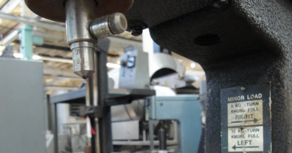
Rockwell C (HRC) presses a diamond cone into the surface under a preload and then a main load of 150 kgf. The depth the cone travels past the preload gives the number. It is quick, needs little surface preparation compared with other methods and is the scale almost every tool steel drawing uses. The method is defined in ASTM E18 and ISO 6508.
Rockwell C is valid from roughly 20 to 70 HRC. Below 20 HRC use a different scale such as Rockwell B. Annealed tool steel at 200 to 250 HB is outside HRC range and is checked on a Brinell or Rockwell B tester instead.
Typical repeatability on a calibrated bench tester is about ±0.5 HRC, but a realistic tolerance on a drawing is a 2 HRC window such as 58 to 60 HRC. A window of 1 HRC is possible but it is a statement about the heat treat furnace, not about the tester.
Vickers: for thin sections, cases and small parts
Vickers (HV) presses a diamond pyramid into the surface under a chosen load, then measures the diagonals of the indent under a microscope. The number comes from the load and the size of the mark. ASTM E92 and ISO 6507 cover the method.
Use Vickers when Rockwell is the wrong tool:
- Thin parts and sharp edges. The Rockwell indent is deep and needs enough steel below it. A pyramid at light load makes a small shallow mark.
- Cases and coatings. A nitrided or carburised surface is a gradient, not a single hardness. Micro Vickers at 0.3 to 1 kgf, taken in steps across a section, plots the profile.
- Very hard steel above 65 HRC. Rockwell C loses accuracy near its upper limit.
Vickers needs a flat, polished surface. That is the reason it is used on sections and samples rather than on every finished part.
Portable testers: for parts too big for a bench
Large plates, rolls and wear parts cannot always go on a bench tester. Two portable methods fill the gap:
- Rebound testers drop a small impact body on the surface and measure how fast it bounces back. They are quick and read out in HRC or HV after conversion.
- Ultrasonic contact impedance (UCI) presses a Vickers diamond on a vibrating rod and measures frequency shift. It reads small indents on smooth surfaces.
Both need calibration on a test block of similar steel and similar mass. The results on a thin or light part can be wrong because the part itself vibrates. Treat portable results as a screen and ask for a bench Rockwell on a coupon or an unused face if the number is a contract acceptance point.
How the scales compare
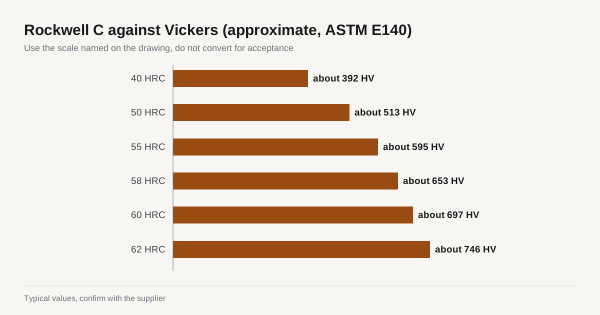
Hardness scales are converted by tables such as ASTM E140. These are approximate for steel and not exact for any given grade, so use them for orientation, not for acceptance.
| HRC | Approx. HV | Typical use |
|---|---|---|
| 40 | 392 | Pre-hardened mold steel, structural parts |
| 50 | 513 | Hot work dies, shock tools |
| 55 | 595 | Forming dies, S7, hardened punches |
| 58 | 653 | Cold work dies, D2 and A2 at working hardness |
| 60 | 697 | High wear tools and blades |
| 62 | 746 | Top range for D2, M2 and cutting tools |
Never convert in the opposite direction on a contract. If a drawing says 700 HV, test in Vickers. If it says 60 HRC, test in Rockwell C.
Where to put the indent
Location is where most disputes start. A few rules keep the testing honest:
- Surface condition. Test on a ground or machined face, flat and clean. Decarburised or oxidised skin from heat treatment reads soft. Remove at least 0.2 to 0.5 mm of surface, or the full stated decarb allowance, before testing.
- Distance from edge. Keep the centre of a Rockwell C indent at least 2.5 mm from any edge and at least 3 mm from the next indent. These are the minimum spacings in ASTM E18 for diamond indenters.
- Thickness. The part should be at least 10 times the indent depth under the indent. For HRC, that is roughly 0.7 to 1 mm of steel.
- Working face. An indent is a small crater. On a polished mold face, a cutting edge or a wear surface it is a defect. Mark the test spot on a non-working face, or on a sacrificial boss, or a test coupon heat treated with the part.
- Curved surfaces. On a small convex cylinder, the reading needs a correction from the standard. Ask the lab to apply the standard correction or test on a flat.
Test coupons and what they prove
For complex parts, a test coupon cut from the same bar and heat treated in the same load is the standard way to avoid marking the part. It proves the furnace hardness. It does not prove that the part itself has the same hardness through a thick section, because mass changes the cooling rate. For large sections ask for testing on the part, on a cut end or an unused face.
If your part is more than 100 mm thick, a surface hardness can hide a soft core. Ask what the section was quenched in and whether a section cut test is planned. Our note on what an inspection report proves explains why a hardness reading alone is not a full proof package.
Why retained austenite and decarb change the reading
Two metallurgical effects move a hardness reading without anything being wrong with the tester. A surface layer that lost carbon in the furnace is softer than the steel underneath, so a test on the as-heat-treated skin reads low. A part with a lot of retained austenite, common in D2 after a high temperature hardening cycle, can read a point or two lower than the same steel with the austenite converted. Neither is a fault in the test method. Both are reasons to test on a ground surface and to keep the heat treat record with the part.
It also helps to understand scatter. Even on a calibrated bench tester, five readings on one part vary by a point or so. A single reading of 57 HRC on a part specified at 58 to 60 is not necessarily a failure. A report that gives three or five readings and the mean is more honest and easier to defend than one number.
Checking the tester itself
Hardness results are only as good as the tester. A bench Rockwell tester is verified against certified reference blocks at stated intervals, and the block hardness should be near the range being tested. For tool steel at 58 to 62 HRC, a block at about 60 HRC is the right check. Ask a supplier whether their tester is verified, how often and against which blocks. A lab that cannot answer that is a lab whose numbers cannot be defended in a dispute.
Writing the callout
A complete hardness callout has five parts:
- Required range (for example 58 to 60 HRC)
- Method (Rockwell C, ASTM E18)
- Location (on face A, or on the test coupon)
- Surface prep (after removing 0.3 mm)
- Reporting (three readings, and the mean)
Every one of these is a possible argument later. The grades page at tool steel grades gives the usual working hardness window for each grade so the range you write is realistic.
Checklist before you send the RFQ
- Hardness range per grade, with realistic window of 2 HRC.
- Test method and standard.
- Where the test may be made and where it must not be.
- Whether a test coupon is acceptable.
- What report format you expect: single number, three readings or a hardness traverse.
Send the drawing through the RFQ form and a written quote comes back within 24 business hours.